What happens in a solar panel, in simple terms, is that photons are being absorbed and displacing electrons within the panel, thus creating an electric current. Within the solar panel are many individual, smaller components called photovoltaic cells. These cells linked together are what form the solar panel. Photovoltaic cells are comprised of two semi-conductive layers, usually made of silicon. When the photons hit these cells however, the electrons need somewhere to go in order to generate a flow of electricity.
To solve this, engineers use the process known as doping to create an electric field within the cell by adding electrons to the top semi-conductive layer, and removing electrons from the bottom semi-conductive layer. This is done by replacing a silicon atom with an atom containing more or less electrons than the silicon atom. Usually, phosphorus is added to the top layer to add electrons, while boron is added to the bottom layer to remove electrons. That way, when photons hit the cell, electrons from the top layer are displaced into the bottom layer to fill the "holes" of missing electrons, thus creating an electric current. Because the top layer has added electrons, it becomes negatively charged. Similarly, the bottom layer becomes positively charged. For this reason, the top and bottom layers are called "n-type" and "p-type" respectively (Figure 1). [Reference 1]
The initial electrical energy created by this solar panel will be measured with a multimeter. This measurement will be used to see the energy efficiency of the entire Artificial Photosynthesis system.
Figure 1: A Photovoltaic Cell using Solar Energy to excite electrons
Electrolysis
After converting the solar energy into electrical energy, the electrical energy would fuel the non-spontaneous reaction of the water solution. This reaction will split off on to the anode and the cathode.
The water solution is comprised for water molecules and an electrolyte (KOH), for an electrolyte will allow the electrical energy to travel between the anode and cathode. The reason KOH is chosen is because it is abundant, cheap, and eco-friendly [Reference 2]. There is also an anode and cathode that are made of stainless steel. It has been decided to use stainless steel over the copper for reasons of being cheaper, less reactive and more effective, in the long term, than copper.
The electrical energy from the electrolysis would cause two reactions in the solution. The transfer of an electric current to conduct these two reactions can be shown in Figure 2. A reaction that would occur towards the anode would involve the splitting of the electrolyte molecules:
Anode Reaction: 4OH- (aq) → O2 (g) + 2H2O (l) + 4e- [Reference 3]
The free electrons that are released from the anode would react with the water molecules on the cathode and cause them to split into oxygen gas (O2) and hydrogen gas (H2) .
Cathode Reaction: 2H2O (l) + 2e- → 2OH- (g) + H2 (g) [Reference 3]
This reaction allows the production of hydrogen gas which is what is needed next in the system. The net voltage required to start this reaction is a sum of the potentials of the anode and cathode reactions:
-0.40 V (Anode) - 0.83 V (Cathode) = -1.23 V (1.23 Volts required) [Reference 4].
Figure 2: Example of Electrolysis being conducted with Water
http://hyperphysics.phy-astr.gsu.edu/hbase/thermo/electrol.html
Fuel Cell
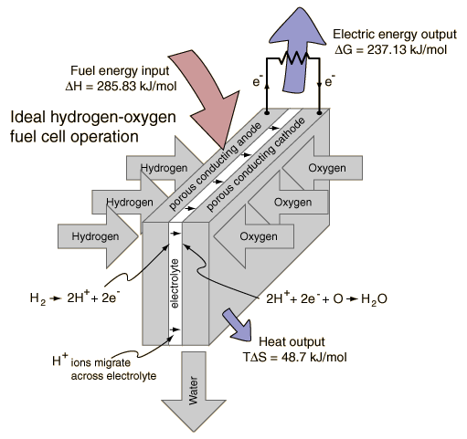
A fuel cell is being used to convert the energy stored in the hydrogen gas back into usable electrical energy. A method is devised for connecting the output of the reactor with the input of the fuel cell so as not to lose any of the products of the electrolysis reaction. Any loss of products would diminish the system’s energy efficiency. Depending on the expected efficiency of the photovoltaic and the reactor, the fuel cell can operate in the system while rated at a lower output because of the energy lost through the first two energy conversions.
A fuel cell is being used to convert the energy stored in the hydrogen gas back into usable electrical energy. A method is devised for connecting the output of the reactor with the input of the fuel cell so as not to lose any of the products of the electrolysis reaction. Any loss of products would diminish the system’s energy efficiency. Depending on the expected efficiency of the photovoltaic and the reactor, the fuel cell can operate in the system while rated at a lower output because of the energy lost through the first two energy conversions.
The hydrogen gas goes in through the anode side of the fuel cell which creates hydrogen ions (H+) and electrons. These electrons are then transported through to the other side of the fuel cell which is the cathode. The cathode is also where the oxygen gas from the reactor comes into the fuel cell. This transfer of electrons from the anode to the cathode through an attached wire will create an electric current. Lastly, the reaction at the cathode creates water as a byproduct from the combination of the hydrogen ions, electrons, and oxygen gas. This entire procedure is shown in detail in Figure 3. [Reference 5]
The fuel cell’s electrical output will be measured and possibly used to turn a motor or light a light bulb as a demonstration of the energy present at the end of the system.
Figure 3: Fuel Cell Diagram http://hyperphysics.phy-astr.gsu.edu/hbase/thermo/electrol.html


No comments:
Post a Comment