The solar panel's wires were connected to the bolt tops on the reactor, and a multimeter--shown in Figure 4--was located next to the reactor with the positive wire attached to the bolt above the anode and the negative wire attached to the cathode bolt. The fuel cell was on the plexiglass adjacent to the reactor and had smaller tubes that allowed for the water vapor to escape (Figure 5).

Figure 1: Solar Panel for Photovoltaic cell placed facing towards sun directly above

Figure 2: Side View of the System

Figure 3: Front View of the System

Figure 4: One of two Multimeters used to measure potential difference and current
 \
\
Figure 5: Smaller tubes on Fuel allowing water vapor to escape
The testing was done by measuring the potential difference (volts) and the current (amperes) of the solar energy of the photovoltaic cell. This allowed electrolysis to commence, and the hydrogen and oxygen gas to flow to there respective sides of the fuel cells with the guidance of the tubes. Another multimeter was used on the each end of the fuel to measure its potential difference and amperes. This measuring process was done for 20 minutes every two minutes. By doing this we could get multiple values of each measurement as the process commenced continuously. After this test, we removed the top end cap to reveal the steel plates to show that little to none of the steel plates were oxidized in the electrolysis reaction (Figures 6 and 7).
We conducted the same test, but with only one plate for each electrode instead of three. This would decrease the surface area which would naturally lower the reaction rate, but this also required less current to run the process through. Before starting, we wiped down each electrode plate with sandpaper to rub off any parts of the steel that may have been oxidized, thus allowing the entire surface to be used in the reaction.
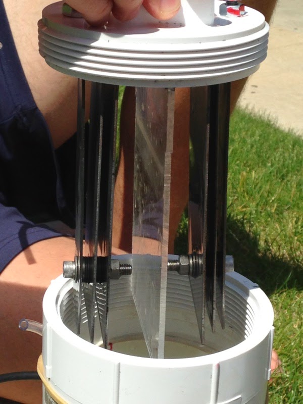
Figure 6: Parallel View of all of the plates of each electrode and plexiglass dividing

Figure 7: Perpendicular View of electrodes and divider that shows surface of steel plates
No comments:
Post a Comment